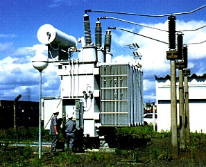
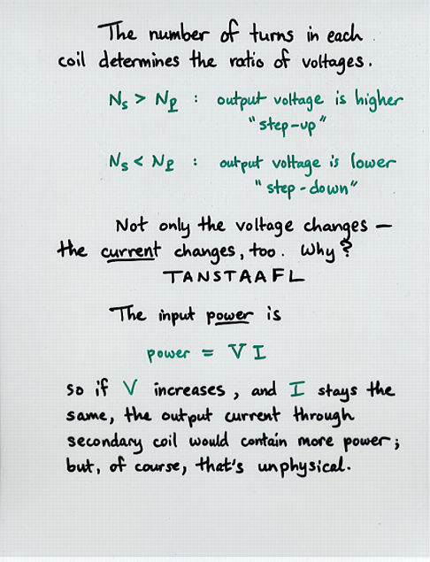
Electrical transformers are used to "transform" voltage from one level to another, usually from a higher voltage to a lower voltage. They do this by applying the principle of magnetic induction between coils to convert voltage and/or current levels.
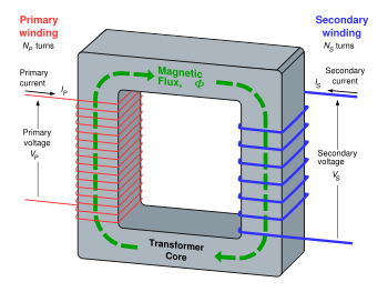
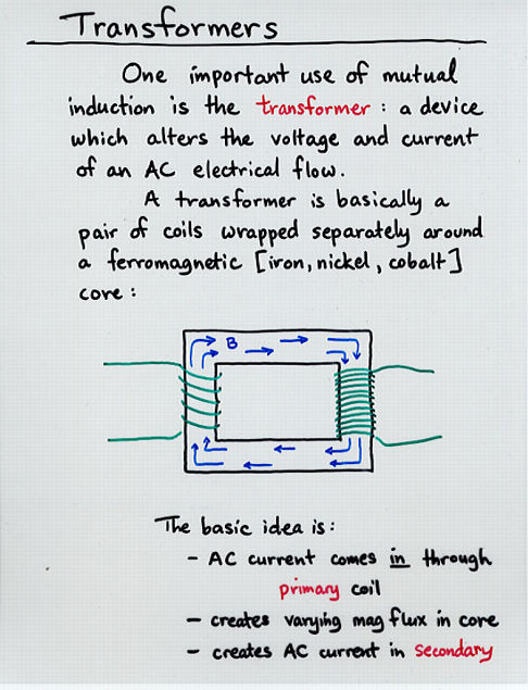
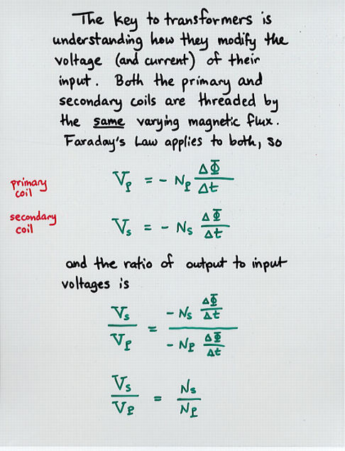
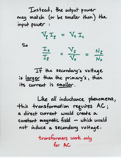
In this way, electrical transformers are a passive device which transforms alternating current (otherwise known as "AC") electric energy from one circuit into another through electromagnetic induction. An electrical transformer normally consists of a ferromagnetic core and two or more coils called "windings". A changing current in the primary winding creates an alternating magnetic field in the core. In turn, the core multiplies this field and couples the most of the flux through the secondary tranformer windings. This in turn induces alternating voltage (or emf) in each of the secondary coils.
Electrical transformers can be configured as either a single-phase or a three-phase configuration. There are several important specifications to specify when searching for electrical transformers. These include: maximum secondary voltage rating, maximum secondary current rating, maximum power rating, and output type. An electrical transformer may provide more than one secondary voltage value. The Rated Power is the sum of the VA (Volts x Amps) for all of the secondary windings. Output choices include AC or DC. For Alternating Current waveform output, voltage the values are typically given in RMS values. Consult manufacturer for waveform options. For direct current secondary voltage output, consult manufacturer for type of rectification.
 Cores can be constructed as either a toroidal or laminated. Toroidal units typically have copper wire wrapped around a cylindrical core so the magnetic flux, which occurs within the coil, doesn't leak out, the coil efficiency is good, and the magnetic flux has little influence on other components. Laminated refers to the laminated-steel cores. These steel laminations are insulated with a nonconducting material, such as varnish, and then formed into a core that reduce electrical losses. There are many types. These include autotransformer, control, current, distribution, general-purpose, instrument, isolation, potential (voltage), power, step-up, and step-down. Mountings include chassis mount, dish or disk mount, enclosure or free standing, h frame, and PCB mount.
Electrical Transformer Grid

©2012 Dennis Caldwell and World of Stock. Unlicensed Use Prohibited More Info |
|
Keywords:
Air, Contamination, Danger, Dump, Electrical,
Electricity, Energy, Environment, Grid, Hazard, Hazardous, Industry,
Materials, Poison, Pollution, Quality, Transformer
stock photo, photos, prints, image, images, pics, photography
Transformers and Long-Distance Power Transmission
 Viewgraph 1
 Viewgraph 2
 Viewgraph 3
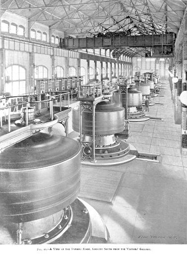
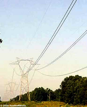
 Viewgraph 4 Let's look very briefly at the steps involved in bringing electricity from a generating station to your home. For the full story, read How Power Distribution Grids Work, in the references below. - Create the electricity: different generators produce different voltages, but a very rough typical value might be 1,000 volts.
- ncIrease voltage via a step-up transformer at an electrical station near the power plant, up to maybe 500,000 volts.
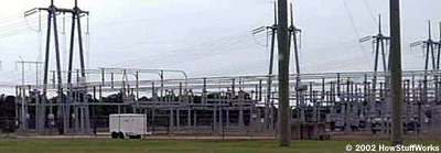
- Send electricity long distance over high-voltage transmission lines.
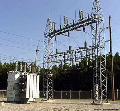
- Decrease voltage at a local substation via a step-down transformer to perhaps 3,000 volts .
- Send electricity a few miles via "telephone poles" (or underground cables.
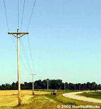
- Divert some electricity to an individual building, decreasing the voltage to 240 volts with another step-down transformer.
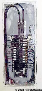
- When it first enters the building, run electricity through a fuse-box or set of circuit breakers. Most of the wiring inside the house is arranged so that it makes use of only 120 volts (read the full article below to see how).
- Provide good ol' 120-volt electricity via standard outlets.
schematic and explanations of three phase transformer
This section will discuss three phase transformers and how to calculate transformer overcurrent protection..
Three Phase Transformers Introduction: Three phase transformers are used throughout industry to change values of three phase voltage and current. Since three phase power is the most common way in which power is produced, transmitted, an used, an understanding of how three phase transformer connections are made is essential. In this section it will discuss different types of three phase transformers connections, and present examples of how values of voltage and current for these connections are computed
Three Phase Transformer Construction: A three phase transformer is constructed by winding three single phase transformers on a single core. These transformers are put into an enclosure which is then filled with dielectric oil. The dielectric oil performs several functions. Since it is a dielectric, a nonconductor of electricity, it provides electrical insulation between the windings and the case. It is also used to help provide cooling and to prevent the formation of moisture, which can deteriorate the winding insulation.
Three-Phase Transformer Connections There are only 4 possible transformer combinations: - Delta to Delta - use: industrial applications
- Delta to Wye - use : most common; commercial and industrial
- Wye to Delta - use : high voltage transmissions
- Wye to Wye - use : rare, don't use causes harmonics and balancing problems.
Three-phase transformers are connected in delta or wye configurations. A wye-delta transformer has its primary winding connected in a wye and its secondary winding connected in a delta (see figure 1-1). A delta-wye transformer has its primary winding connected in delta and its secondary winding connected in a wye (see figure 1-2).
| Figure 1-1: Wye-Delta connection |
| Figure 1-2: Delta-Wye connection |
Delta Conections:
A delta system is a good short-distance distribution system. It is used for neighborhood and small commercial loads close to the supplying substation. Only one voltage is available between any two wires in a delta system. The delta system can be illustrated by a simple triangle. A wire from each point of the triangle would represent a three-phase, three-wire delta system. The voltage would be the same between any two wires (see figure 1-3).
Wye Connections:
In a wye system the voltage between any two wires will always give the same amount of voltage on a three phase system. However, the voltage between any one of the phase conductors (X1, X2, X3) and the neutral (X0) will be less than the power conductors. For example, if the voltage between the power conductors of any two phases of a three wire system is 208v, then the voltage from any phase conductor to ground will be 120v. This is due to the square root of three phase power. In a wye system, the voltage between any two power conductors will always be 1.732 (which is the square root of 3) times the voltage between the neutral and any one of the power phase conductors. The phase-to-ground voltage can be found by dividing the phase-to-phase voltage by 1.732 (see figure 1-4).
Connecting Single-Phase Transformers into a Three-Phase Bank: If three phase transformation is need and a three phase transformer of the proper size and turns ratio is not available, three single phase transformers can be connected to form a three phase bank. When three single phase transformers are used to make a three phase transformer bank, their primary and secondary windings are connected in a wye or delta connection. The three transformer windings in figure 1-5 are labeled H1 and the other end is labeled H2. One end of each secondary lead is labeled X1 and the other end is labeled X2.
Figure 1-6 shows three single phase transformers labeled A, B, and C. The primary leads of each transformer are labeled H1 and H2 and the secondary leads are labeled X1 and X2. The schematic diagram of figure 1-5 will be used to connect the three single phase transformers into a three phase wye-delta connection as shown in figure 1-7.
The primary winding will be tied into a wye connection first. The schematic in figure 1-5 shows, that the H2 leads of the three primary windings are connected together, and the H1 lead of each winding is open for connection to the incoming power line. Notice in figure 1-7 that the H2 leads of the primary windings are connected together, and the H1 lead of each winding has been connected to the incoming primary power line.
Figure 1-5 shows that the X1 lead of the transformer A is connected to the X2 lead of transformer c. Notice that this same connection has been made in figure 1-7. The X1 lead of transformer B is connected to X2, lead of transformer A, and the X1 lead of transformer B is connected to X2 lead of transformer A, and the X1 lead of transformer C is connected to X2 lead of transformer B. The load is connected to the points of the delta connection. Open Delta Connection: The open delta transformer connection can be made with only two transformers instead of three (figure 1-8). This connection is often used when the amount of three phase power needed is not excessive, such as a small business. It should be noted that the output power of an open delta connection is only 87% of the rated power of the two transformers. For example, assume two transformers, each having a capacity of 25 kVA, are connected in an open delta connection. The total output power of this connection is 43.5 kVA (50 kVA x 0.87 = 43.5 kVA).
| Figure 1-8: Open Delta Connection |
Another figure given for this calculation is 58%. This percentage assumes a closed delta bank containing 3 transformers. If three 25 kVA transformers were connected to form a closed delta connection, the total output would be 75 kVA (3 x 25 = 75 kVA). If one of these transformers were removed and the transformer bank operated as an open delta connection, the output power would be reduced to 58% of its original capacity of 75 kVA. The output capacity of the open delta bank is 43.5 kVA (75 kVA x .58% = 43.5 kVA).
The voltage and current values of an open delta connection are computed in the same manner as a standard delta-delta connection when three transformers are employed. The voltage and current rules for a delta connection must be used when determining line and phase values of voltage current. Closing a Delta: When closing a delta system, connections should be checked for proper polarity before making the final connection and applying power. If the phase winding of one transformer is reversed, an extremely high current will flow when power is applied. Proper phasing can be checked with a voltmeter at delta opening. If power is applied to the transformer bank before the delta connection is closed, the voltmeter should indicate 0 volts. If one phase winding has been reversed, however, the voltmeter will indicate double the amount of voltage.
It should be noted that a voltmeter is a high impedance device. It is not unusual for a voltmeter to indicate some amount of voltage before the delta is closed, especially if the primary has been connected as a wye and the secondary as a delta. When this is the case, the voltmeter will generally indicate close to the normal output voltage if the connection is correct and double the output voltage if the connection is incorrect. Over current Protection for the Primary: Electrical Code Article 450-3(b) states that each transformer 600 volts, nominal or less, shall be protected by an individual overcurrent device on the primary side, rated or set at not more than 125% of the rated primary current of the transformer. Where the primary current of a transformer is 9 amps or more and 125% of this current does not correspond to a standard rating of a fuse or nonadjustable circuit breaker, the next higher standard rating shall be permitted. Where the primary current is less than 9 amps, an overcurrent device rated or set at not more than 167% of the primary current shall be permitted. Where the primary current is less than 2 amps, an overcurrent device rated or set at not more than 300% shall be permitted.
Example #1:
What size fuses is needed on the primary side to protect a 3 phase 480v to 208v 112.5 kVA transformer?
* Important when dealing with 3 phase applications always use 1.732 (square root of 3).
To solve: P / I x E
112.5 kVA X 1000 = 112500 VA
112500 VA divided by 831 (480 x 1.732) = 135.4 amps
Since the transformer is more than 9 amps you have to use 125 %.
135.4 X 1.25 = 169 amps.
Answer: 175 amp fuses (the next higher standard, Electrical Code 240-6). Example #2:
What size breaker is needed on the primary side to protect a 3 phase 208v to 480v 3kVA transformer?
To solve: P / I x E
3kVA X 1000 = 3000 VA
3000 VA divided by 360 (208 x 1.732) = 8.3 amps
Since the transformer is 9 amps or less you have to use 167%.
8.3 X 1.67 = 13.8 amps
Answer: 15 amp breaker (preferably a 20 amp breaker) Electrical Code Article 450-3(b)(2) states if a transformer 600 v, nominal, or less, having a an overcurrent device on the secondary side rated or set at not more than 125% of the rated secondary current of the transformer shall not be required to have an individual overcurrent device on the primary side if the primary feeder overcurrent device is rated or set at a current value not more than 250% of the rated primary current of the transformer. Over current Protection for the Secondary: Electrical Code Article 450-3(b)(2) states that a transformer 600 v, nominal, or less, shall be protected by an individual overcurrent device on the secondary side, rated or set at not more than 125% of the rated secondary current of the transformer. Where the secondary current of a transformer is9 amps or more and 125% of this current does not correspond to a standard rating of a fuse or nonadjustable circuit breaker, the next higher standard rating shall be permitted. Where the secondary current is less than 9 amps, an overcurrent device rated or set at not more than 167% of the secondary current shall be permitted.
Example:
What size breaker is needed on the secondary side to protect a 3 phase 480v/208v 112.5 kVA transformer?
To solve : P / I x E
112.5 kVA x 1000 = 112500 VA
112500 divided by 360 (208 x 1.732) = 312.5 amps
312.5 X 1.25 = 390.6 amps
Answer: 400 amp breaker. 3 phase 4 wires,open delta connection.

|
|


No comments:
Post a Comment